AM SERIES – AIR AMPLIFIERS

POWERFUL, ADJUSTABLE AND EASILY CONNECTED TO COOLING TUBES IN A PATENTED SYSTEM

am uniti
  • Construction shape optimised to maximise the Coanda effect

  • Possibility to regulate the flow with an adjustable ring

  • Wide vacuum and blow-off section, suitable for a variety of applications

  • Instant operation

  • No moving parts, so not subject to wear

  • No electricity or chemical products required

  • More efficient than Venturi devices and enjectors

  • No sparks or interferences

  • Reliable and maintenance-free

DESCRIPTION AIR AMPLIFIERS

The AM Series round air-flow amplifiers offer excellent performance for suction and blow-off. The quality of the design and construction optimise the Coanda effect so they use a small amount of compressed air to generate a powerful, high-speed flow. They perform a dual function of vacuum and blow-off: for ventilating electrical panels, conveying fumes and lightweight particles produced by machining, conveying and handling of light parts, drying and cooling. When combined with the VR Series coolers, they create an effective patented system where, by conveying the flow of hot air discharged by the cooler and feeding it into the AM Series amplifier, the cooling power is optimised, so making it possible to drawn hot air out of enclosures or ventilating closed areas to be cooled. The air flow rate can be adjusted by simply turning the nut at the inlet.


Part number AM-10T
General characteristics
Materials Aluminium
Air supply port G-1/8" F
Inlet diameter Ø-19
Outlet diameter Ø-19
Air supply pressure max. 7 bar
Recommended tube Ø-6x1 - Ø-8x1
Size values ↓ download
Supply pressure Opening adjustment Vacuum at inlet Flow rate Air consumptio Amplification ratio
[bar] [mm] [mbar] [Stm3/h] [l/min] [l/min]
2 Min -49,0 53,0 883,3 105,0 8,4
Intermediate -65,0 76,0 1200,7 221,0 5,7
Max -71,0 73,0 1216,7 377,0 3,2
3 Min -75,0 66,5 1108,3 155,0 7,2
Intermediate -99,0 91,0 1516,7 318,0 4,8
Max -112,0 93,0 1550,0 502,0 3,1
4 Min -101,5 77,0 1283,3 211,0 6,1
Intermediate -129,5 104,0 1733,3 466,0 3,7
Max -144,0 106,0 1766,7 633,0 2,8
5 Min -121,0 86,0 1433,3 244,0 5,9
Intermediate -173,5 116,0 1933,3 563,0 3,4
Max -255,0 126,0 2091,7 764,0 2,7
6 Min -145,0 94,0 1558,3 304,0 5,1
Intermediate -193,5 133,0 2216,7 676,0 3,3
Max -251,0 135,0 2250,0 863,0 2,6
7 Min -167,5 101,0 1675,0 370,0 4,5
Intermediate -246,0 149,0 2483,3 770,0 3,2
Max -274,0 153,0 2541,7 977,0 2,6

Part number AM-15T
General characteristics
Materials Aluminium
Air supply port G-1/8" F
Inlet diameter Ø-19
Outlet diameter Ø-19
Air supply pressure max. 7 bar
Recommended tube Ø-8x1 - Ø-10x1
Size values ↓ download
Supply pressure Opening adjustment Vacuum at inlet Flow rate Air consumptio Amplification ratio
[bar] [mm] [mbar] [Stm3/h] [l/min] [l/min]
2 Min -80,0 33,5 558,3 78,3 7,1
Intermediate -91,5 46,0 766,7 158,3 4,8
Max -98,0 46,0 766,7 220,0 3,5
3 Min -120,0 38,0 633,3 110,0 5,8
Intermediate -139,0 48,0 800,0 220,0 3,6
Max -156,0 50,0 833,3 305,0 2,7
4 Min -160,0 42,0 700,0 138,3 5,1
Intermediate -180,0 50,0 833,3 283,3 2,9
Max -194,0 52,0 866,7 383,3 2,3
5 Min -187,0 46,0 766,7 163,3 4,7
Intermediate -219,0 52,0 866,7 343,3 2,5
Max -333,0 56,0 933,3 461,7 2,0
6 Min -224,0 47,0 783,3 191,7 4,1
Intermediate -249,0 56,0 933,3 403,3 2,3
Max -360,0 60,0 1000,0 543,3 1,8
7 Min -256,0 49,0 816,7 223,3 3,7
Intermediate -345,0 58,0 966,7 456,7 2,1
Max -377,0 65,0 1083,3 620,0 1,7

Part number AM-20T
General characteristics
Materials Aluminium
Air supply port G-1/4" F
Inlet diameter Ø-32
Outlet diameter Ø-32
Air supply pressure max. 7 bar
Recommended tube Ø-8x1 - Ø-10x1
Size values ↓ download
Supply pressure Opening adjustment Vacuum at inlet Flow rate Air consumptio Amplification ratio
[bar] [mm] [mbar] [Stm3/h] [l/min] [l/min]
1 Min -8,5 32,0 533,3 58,3 9,1
Intermediate -17,0 60,0 1000,0 116,7 8,6
Max -14,0 50,0 833,3 333,3 2,5
2 Min -18,0 72,0 1200,0 125,0 9,6
Intermediate -39,0 106,0 1766,7 283,3 6,2
Max -44,0 100,0 1666,7 533,3 3,1
3 Min -30,0 95,0 1583,3 200,0 7,9
Intermediate -59,0 134,0 2233,3 416,7 5,4
Max -68,0 136,0 2266,7 700,0 3,2
4 Min -43,0 112,0 1866,7 283,3 6,6
Intermediate -79,0 158,0 2633,3 650,0 4,1
Max -93,0 160,0 2666,7 883,3 3,0
5 Min -55,0 126,0 2100,0 325,0 6,5
Intermediate -128,0 180,0 3000,0 783,3 3,8
Max -177,0 195,0 3250,0 1066,7 3,0
6 Min -66,0 140,0 2333,3 416,7 5,6
Intermediate -138,0 210,0 3500,0 950,0 3,7
Max -141,0 210,0 3500,0 1183,3 3,0
7 Min -79,0 152,0 2533,3 516,7 4,9
Intermediate -147,0 240,0 4000,0 1083,3 3,7
Max -171,0 240,0 4000,0 1333,3 3,0

Part number AM-20T
General characteristics
Materials Aluminium
Air supply port G-1/4" F
Inlet diameter Ø-32
Outlet diameter Ø-32
Air supply pressure max. 7 bar
Recommended tube Ø-10x1 - Ø-12x1
Size values ↓ download
Supply pressure Opening adjustment Vacuum at inlet Flow rate Air consumptio Amplification ratio
[bar] [mm] [mbar] [Stm3/h] [l/min] [l/min]
1 Min -7,0 84,0 1400,0 170,7 8,2
Intermediate -16,0 166,0 2766,7 342,0 8,1
Max -12,0 112,0 1866,7 650,0 2,9
2 Min -16,5 148,0 2400,7 296,0 8,3
Intermediate -37,0 249,0 4150,0 608,0 6,8
Max -42,0 193,0 3208,3 1058,0 3,0
3 Min -60,0 213,0 3541,7 450,0 7,9
Intermediate -65,9 319,0 5316,7 908,0 5,9
Max -67,0 283,0 4708,3 1541,0 3,1
4 Min -41,5 245,0 4083,3 671,7 6,1
Intermediate -74,5 331,0 5516,7 1375,0 4,0
Max -87,0 346,0 5758,3 1917,0 3,0
5 Min -52,5 288,0 4800,0 787,5 6,1
Intermediate -124,0 390,0 6500,0 1641,7 4,0
Max -144,0 1413,0 6875,0 2283,0 3,0
6 Min -63,0 313,0 5208,3 1017,0 5,1
Intermediate -134,0 396,0 6600,0 2091,5 3,2
Max -138,0 468,0 7800,0 2608,0 3,0
7 Min -70,4 366,0 6100,0 1225,0 5,0
Intermediate -143,5 468,0 7800,0 2475,0 3,2
Max -151,0 555,0 9250,0 3083,0 3,0

Part number AM-30T
General characteristics
Materials Aluminium
Air inlet port G-1/4" F
Inlet diameter Ø-38
Outlet diameter Ø-38
Air supply pressure max. 7 bar
Recommended hose Ø-10x1 - Ø-12x1
Size values ↓ download
Supply pressure Opening adjustment Vacuum at inlet Flow rate Air consumption Amplification ratio
[bar] [mm] [mbar] [Stm3/h] [l/min] [l/min]
1 Min -6,0 136,0 2264,0 283,0 8,0
Intermediate -15,0 272,0 4536,0 567,0 8,0
Max -10,0 174,0 2901,0 967.0 3,0
2 Min -15,0 224,0 3736,0 467,0 8.0
Intermediate -35,0 392,0 6531,0 933,0 7,0
Max -40,0 285,0 4749,0 1583,0 3,0
3 Min -30,0 336,0 5600,0 700,0 8,0
Intermediate -60,0 504,0 8400,0 1400,0 6,0
Max -65,0 429,0 7149,0 2383,0 3,0
4 Min -40,0 378,0 6300,0 1050,0 6,0
Intermediate -70,0 504,0 8400,0 2100,0 4,0
Max -80,0 531,0 8850,0 2950,0 3,0
5 Min -50,0 450,0 7500,0 1250,0 6,0
Intermediate -120,0 600,0 10000,0 2500,0 4,0
Max -110,0 630,0 10500,0 3500,0 3,0
6 Min -60,0 485,0 8085,0 1617,0 5,0
Intermediate -130,0 582,0 9699,0 3233,0 3,0
Max -135,0 726,0 12099,0 4033,0 3,0
7 Min -70,0 580,0 9665,0 1933,0 5,0
Intermediate -140,0 696,0 11601,0 3867,0 3,0
Max -130,0 870,0 14499,0 4833,0 3,0

Part number AM-40T
General characteristics
Materials Aluminium
Air inlet port G-3/8" F
Inlet diameter Ø-50
Outlet diameter Ø-50
Air supply pressure max. 7 bar
Recommended tube Ø-12x1 - Ø-14x1
Size values ↓ download
Supply pressure Opening adjustment Pressure drop in input Flow rate Air consumption Amplification ratio
[bar] [mm] [mbar] [Stm3/h] [Nl/min] [Nl/min]
1 Min -6,0 328,0 5464,0 683,0 8,0
Intermediate -15,0 656,0 10936,0 1367,0 8,0
Max -10,0 417,0 6951,0 2317.0 3,0
2 Min -15,0 520,0 8664,0 1083,0 8.0
Intermediate -35,0 910,0 15169,0 2167,0 7,0
Max -40,0 663,0 11049,0 3683,0 3,0
3 Min -30,0 680,0 11336,0 1417,0 8,0
Intermediate -60,0 1020,0 16998,0 2833,0 6,0
Max -65,0 867,0 14451,0 4817,0 3,0
4 Min -40,0 636,0 10602,0 1767,0 6,0
Intermediate -70,0 848,0 14132,0 3533,0 4,0
Max -80,0 891,0 14850,0 4950,0 3,0
5 Min -50,0 744,0 12402,0 2067,0 6,0
Intermediate -120,0 992,0 16532,0 4133,0 4,0
Max -110,0 1041,0 17349,0 5783,0 3,0
6 Min -60,0 750,0 12500,0 2500,0 5,0
Intermediate -130,0 900,0 15000,0 5000,0 3,0
Max -135,0 1125,0 18750,0 6250,0 3,0
7 Min -70,0 900,0 15000,0 3000,0 5,0
Intermediate -140,0 1080,0 18000,0 6000,0 3,0
Max -130,0 1350,0 22500,0 7500,0 3,0

Part number AM-50T
General characteristics
Materials Aluminium
Air inlet port G-3/8" F
Inlet diameter Ø-63
Outlet diameter Ø-63
Air supply pressure max. 7 bar
Recommended tube Ø-10x1 - Ø-12x1
Size values ↓ download
Supply pressure Opening adjustment Pressure drop in input Flow rate Air consumption Amplification ratio
[bar] [mm] [mbar] [Stm3/h] [Nl/min] [Nl/min]
1 Min -6,0 361,0 6010,0 751,0 8,0
Intermediate -15,0 722,0 11040,0 1504,0 8,0
Max -10,0 459,0 7646,0 2549.0 3,0
2 Min -15,0 572,0 9750,0 1191,0 8.0
Intermediate -35,0 1001,0 16708,0 2384,0 7,0
Max -40,0 729,0 12154,0 4051,0 3,0
3 Min -30,0 748,0 12470,0 1559,0 8,0
Intermediate -60,0 1122,0 18698,0 3116,0 6,0
Max -65,0 954,0 15896,0 5299,0 3,0
4 Min -40,0 700,0 11552,0 1944,0 6,0
Intermediate -70,0 933,0 15545,0 3886,0 4,0
Max -80,0 980,0 16335,0 5445,0 3,0
5 Min -50,0 818,0 13642,0 2274,0 6,0
Intermediate -120,0 1091,0 18185,0 4546,0 4,0
Max -110,0 1145,0 19084,0 6361,0 3,0
6 Min -60,0 825,0 13750,0 2750,0 5,0
Intermediate -130,0 990,0 16500,0 5500,0 3,0
Max -135,0 1238,0 20625,0 6875,0 3,0
7 Min -70,0 990,0 16500,0 3300,0 5,0
Intermediate -140,0 1188,0 19800,0 6600,0 3,0
Max -130,0 1485,0 24750,0 8250,0 3,0

CUMULATIVE PART NO. TABLE

Part number Connections Ø Hose
Supply Ø input Ø output recommended
AM-10T G-1/8" F 19 19 Ø-6x1 - Ø-8x1
AM-15T G-1/8" F 19 19 Ø-8x1 - Ø-10x1
AM-20T G-1/4"F 32 32 Ø-8x1 - Ø-10x1
AM-25T G-1/4"F 32 32 Ø-10x1 - Ø-12x1
AM-30T G-1/4"F 38 38 Ø-10x1 - Ø-12x1
AM-40T G-3/8"F 50 50 Ø-12x1 - Ø-14x1
AM-50T G-3/8"F 63 63 Ø-10x1 - Ø-12x1

Super-Rapid connector

MALE STRAIGHT CONNECTOR WITH O-RING
Part number Tube Thread
6512 6 1/8
6512 8 1/8
6512 8 1/4

Super-Rapid connector

ELBOW SWIVEL MALE, CYLINDRICAL WITH O-RING
Part number Tube Thread
6522 6 1/8
6522 8 1/8
6522 8 1/4

Cooler Air Saving – Patented system

VR Series coolers and AM Series amplifiers used together to pump cool air and extract warm air from an electrical cabinet at the same time, using a single compressed air delivery duct.

  • Effective electrical cabinet ventilation
  • Reduction of compressed air consumption
  • Optimised cooling results

No matter how much cool air is pumped into an electrical cabinet, the effectiveness and efficiency of cooling will never be optimal unless the warm air generated by the electrical components is not properly ventilated at the same time. With ventilation we mean both the creation of convection flows inside the cabinet which effectively distribute the air around the components and the actual extraction of warm air from the cabinet itself.

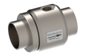
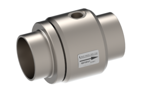
Using the Cooler Air Saving patented system by Simian Project, two results are obtained: the first, using the VR Series coolers, is the rapid, precise cooling of the components which heat the cabinet the most, due to the flexibility of installation (brackets and magnets) and the fact that the flow of cool air onto the main heat sources can be precisely directed (using adjustable nozzles); the second is the proper ventilation of the electrical cabinet given the extraction and blowing power generated by the AM Series air flow amplifiers, fed directly by the air flow discharged from the cooler.


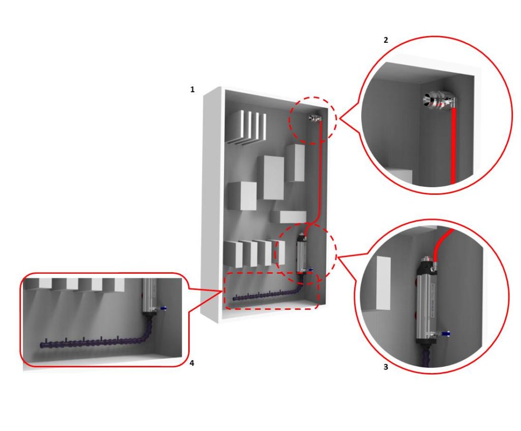
The diagram depicts the system set up inside an electrical cabinet:

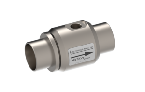
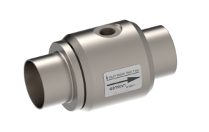
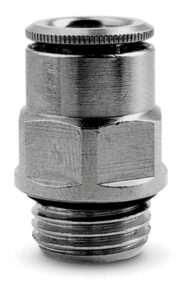
  • The VRX-500 cooler (fig.1) is fed externally with compressed air; the flow of cool air is directed, using special adjustable nozzles, onto the electrical components which give off the most heat, whilst the discharge of warm exhaust air is channelled by the red pipe (fig. 3) and fed into the AM Series amplifier
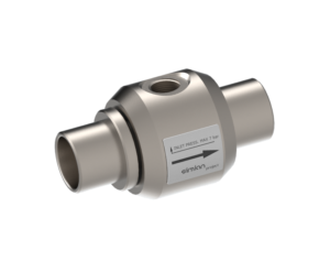
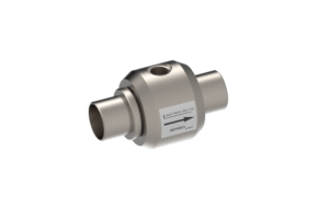
  • The amplifier (fig.2) is fitted in the top right-hand side of the electrical cabinet; the feed-through fitting allows it to intake and extract air from the cabinet; in the example of the diagram, its position in the upper part of the cabinet ensures that extraction occurs where the most hot air accumulates and that even the electrical components located on the opposite side to the direct source of cool air remain at a temperature suitable for optimal functioning

Even where feed-through fitting is not possible (for example in the event of installations in cabinets where IP protection must be guaranteed), the fitting of the amplifier inside the cabinet ensures forced recycling of air, which eliminates the concentration of warm air in the areas located furthest away from sources of cool air.

The patented system also works well together with industrial air-conditioners in electrical cabinets with the following characteristics:

  • Large electrical cabinets where the cool air generated by the air-conditioner has trouble reaching all parts of the cabinet.
  • Electrical cabinets with electrical components laid out in such a way that the convection of air around the components is tricky
  • Electrical cabinets where the heat is generated by a few components which are located far from the area where the air-conditioner pumps in the cool air

N.B.: the Cooler Air Saving system works with VRX-300, VRX-500 and VRX-1000 coolers together with AM-20 and AM-40 amplifiers

Contact us

We will be glad to give you more information about our products!